


Inline spring-loaded check valves help prevent reverse flow by closing automatically when forward pressure drops below the force required to keep the valve open. Proper selection is essential because installation position, cracking pressure, flow conditions, materials, sizing, and fluid quality can all affect valve performance and service life.
Unlike check valves that rely primarily on gravity or reverse flow to close, a spring-loaded design uses a spring to move the valve toward the closed position. This allows the valve to operate in horizontal or vertical piping when the spring is correctly selected for the application.
How Do You Select an Inline Spring-Loaded Check Valve?
Select an inline spring-loaded check valve by evaluating the piping orientation, flow profile, process media, valve and seat materials, cracking pressure, required flow capacity, and fluid cleanliness.
The 7 primary considerations are:
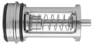
Inline spring-loaded check valve
What Is an Inline Spring-Loaded Check Valve?
An inline spring-loaded check valve is an automatic, one-directional valve designed to allow forward flow and limit reverse flow. The internal spring applies force to the valve trim, helping return the valve to the closed position as forward pressure decreases.
The pressure required to begin opening the valve is known as the cracking pressure. Once flow and differential pressure increase sufficiently, the valve continues opening until it reaches the position required for the application.
Spring-loaded check valves may be used in liquid or gas systems where compact installation, controlled closing, and flexible mounting orientation are important.
Inline Spring-Loaded Check Valve Selection Overview
| Consideration | Why It Matters | What to Review |
|---|---|---|
| Installation position | Orientation and retained liquid can affect the spring force required to close or hold the valve. | Horizontal, vertical-up, or vertical-down installation |
| Flow profile | Disturbed flow may reduce stability and increase wear. | Distance from elbows, tees, pumps, and other disturbances |
| Materials | Body, trim, and seat materials must tolerate the process and surrounding environment. | Media, temperature, concentration, corrosion, and contamination |
| Seat and leakage | Different seat designs provide different leakage performance. | Metal, PTFE, or resilient seat requirements |
| Sizing and spring | An improperly sized valve may not open fully or may experience unstable operation. | Flow rate, pressure drop, line size, and cracking pressure |
| Shock loading | Rapid pressure pulses can create damaging impact forces. | Reciprocating equipment and pulsating discharge conditions |
| Fluid quality | Debris can interfere with closing, sealing, and internal movement. | Solids, fibers, sand, scale, and upstream filtration |
7 Considerations for Applying Inline Spring-Loaded Check Valves
1. Installation Position and Mounting
Inline spring-loaded check valves can be used in horizontal or vertical piping when the spring is correctly selected for the installation.
Orientation is especially important in vertical-down-flow applications. The spring must be strong enough to support the weight of the internal trim in addition to any column of liquid the system is intended to retain.
Review:
- Flow direction
- Horizontal or vertical orientation
- Weight of the valve trim
- Liquid column acting on the valve
- Required cracking and resealing pressure
Do not assume that the same spring is appropriate for every mounting orientation.
2. Elbows, Tees, Pumps, and Other Flow Disturbances
Inline spring-loaded check valves perform best with fully developed flow. Turbulence, swirl, and uneven velocity profiles may affect valve stability and increase wear.
Flow disturbances may be created by:
- Elbows
- Tees
- Reducers
- Centrifugal pumps
- Control valves
- Other upstream piping components
Although the required straight-pipe distance varies with the medium, pipe roughness, velocity, and system design, approximately 10 pipe diameters of straight piping immediately upstream of the valve is commonly recommended for this type of application.
The final piping arrangement should be reviewed against the valve manufacturer’s instructions and actual system conditions.
3. Valve Material Selection
Valve body and trim materials must be compatible with both the process medium and the surrounding environment.
Material resistance can be affected by:
- Operating temperature
- Fluid concentration
- Aeration
- Contaminants
- Interaction between process chemicals
- External atmosphere
- Cleaning or washdown practices
A material that performs well in one concentration or temperature range may not be appropriate under different conditions. Consult an experienced application specialist or the manufacturer’s compatibility guidance before final selection.
4. Seat Material and Leakage Requirements
Inline spring-loaded check valves may be available with metal, PTFE, or resilient seat options. Seat selection affects chemical compatibility, temperature capability, wear resistance, and allowable leakage.
For the valve designs discussed in the original application guidance:
- Metal-to-metal and PTFE O-ring seats may allow leakage of up to 190 cc per minute per inch of line size when tested with air at 80 psi.
- Resilient O-ring seats may provide bubble-tight shutoff, defined as no visible leakage during the specified 80 psi air test.
These values should not be applied universally to every check valve. Confirm the leakage rating and test method for the exact valve model, seat material, line size, and applicable standard.
5. Valve Sizing and Spring Cracking Pressure
Correct sizing is important for stable valve operation, reliable closing, and acceptable service life.
The valve should be sized so it opens sufficiently under normal flow conditions. For the design discussed in the original technical guidance, full opening occurs when the pressure drop across the valve reaches or exceeds approximately 3 times the spring cracking pressure.
When selecting the valve and spring, evaluate:
- Minimum, normal, and maximum flow rates
- Available differential pressure
- Allowable system pressure drop
- Fluid density and viscosity
- Line size
- Required cracking pressure
- Installation orientation
An oversized valve may not open fully at normal flow, which can contribute to unstable movement and accelerated wear. Selecting only by pipe size may not produce the best result.
What Is Cracking Pressure?
Cracking pressure is the minimum differential pressure required to begin opening a spring-loaded check valve.
A lower cracking pressure allows the valve to begin opening with less differential pressure. A stronger spring increases the force required to open the valve and may be needed for certain orientations, backpressure conditions, or retained liquid columns.
The cracking pressure must be high enough to support the application but low enough to allow the required forward flow without excessive pressure loss.
6. Shock-Load and Pulsating Applications
Inline spring-loaded check valves are not necessarily designed for severe shock-load environments, such as the direct discharge of a reciprocating air compressor.
Rapid pressure changes and repeated pulses can create excessive impact stress on the spring, guide, seat, and other internal components. This may reduce valve life or affect sealing and operation.
Before using an inline check valve in a pulsating system, review:
- Pulse frequency
- Peak pressure
- Pressure rise rate
- Flow reversal
- Valve closing speed
- Manufacturer approval for the application
A different check-valve design, pulsation control device, or system arrangement may be required for severe shock-loading conditions.
7. Fluid Quality and Filtration
Inline spring-loaded check valves are best suited to clean liquids and gases.
Contaminants such as sand, fibers, scale, rust, or other debris may:
- Prevent the valve from sealing properly
- Become trapped between the seat and closure element
- Erode internal components
- Restrict valve travel
- Damage the spring or guide surfaces
Where solids may be present, appropriate filtration or separation should be installed upstream of the valve. Filter selection and maintenance should reflect the particle size, contaminant load, fluid, and required system cleanliness.
Common Inline Spring-Loaded Check Valve Applications
Properly selected inline spring-loaded check valves may be used in applications such as:
- Pump discharge lines
- Process piping
- Water and wastewater systems
- Chemical-processing systems
- Compressed-air and gas lines
- Utility and auxiliary systems
- Vertical piping installations
- Systems requiring controlled cracking pressure
Application suitability depends on pressure, temperature, medium, flow conditions, required shutoff performance, and valve construction.
Inline Check Valve Selection Checklist
Before specifying an inline spring-loaded check valve, confirm:
- Process fluid or gas
- Operating and design temperature
- Minimum, normal, and maximum pressure
- Minimum, normal, and maximum flow
- Required cracking pressure
- Allowable pressure drop
- Horizontal or vertical mounting
- Body, trim, spring, and seat materials
- Required leakage or shutoff rating
- Distance from upstream flow disturbances
- Potential shock or pulsation
- Fluid cleanliness and filtration
- Inspection and maintenance access
Get Check Valve Selection Support from MCE
Check valve performance depends on more than line size. MCE can help evaluate the fluid, flow rate, pressure, cracking pressure, orientation, materials, seat design, and installation conditions before a valve is selected.
MCE flow control support includes:
- Check valve selection and application review
- Valve and seat material evaluation
- Cracking-pressure and spring selection
- Flow and pressure-drop considerations
- Replacement and retrofit support
- Related valves, automation, instrumentation, and flow-control equipment
Explore MCE valve capabilities or contact MCE to discuss your inline spring-loaded check valve application.