From Parker Hannifin TechConnect Team and MCE’s Fluid Power Team
Hydraulic, pneumatic or lubrication systems should be efficient and leak free. Sometimes, they are not, because of improper tube line routing—the result of either lack of knowledge, or corners cut on planning time, or both. What can go wrong if routing is not done properly? All kinds of things! From not being able to access fittings for efficient maintenance all the way to leaking connections, inefficient or poor tube routing can create unintended issues that need to be addressed. An ounce of planning is worth a pound of troubleshooting.
Leaking like a Sieve
Case-in-point: A connection in a million-dollar test stand used to test transmission systems was “leaking like a sieve,” according to a puzzled plant engineer. This involved two ports directly across from each other—a very short distance between them—connected by a straight routing using a large (2-inch) OD line. Everything was tightened properly, but the connections kept leaking. It turns out, vibration along the line caused the joints to loosen over time. So while the existing straight line seemed like the most logical design because it was the most direct path, actually the appropriate design necessitated adding a U-bend in the tubing and incorporating elbow fittings—providing “give” to the line. With this fix, the system no longer leaked.
Yes, planning tube line routing is a time investment, but it can have a big ROI—especially for complex systems. During system design, routing should be developed as the next step after sizing the tube lines and selecting the appropriate fittings.
Match tube routing design to the application
Usually, when planning tube line routing, you should follow the rule that fewer joints = fewer leaks. (Makes sense, right? Minimize possible points of failure.) By following this rule, your routing design will often be less likely to leak, will take less time to assemble and maintain and will result in reduced pressure drop/turbulence. But, as the story above illustrates, simpler is not always better; the key is appropriate design for the specific application.
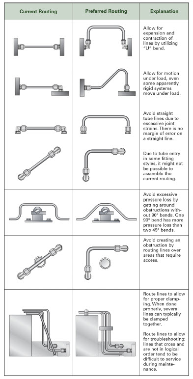
Here are guidelines for planning appropriate tube line routing:
- Leave fitting joints as accessible as possible. Inaccessible joints are difficult and time-consuming to assemble, tighten and service.
- Use software tools to make labor-intensive calculations such as pressure drop.
- Employ U-bends to allow for line contraction and expansion.
- Include offset bends to allow for motion under load, regardless of how ‘rigid’ the system seems.
- Favor bends rather than straight tube lines, because a straight line tube assembly with no bends, like the example of the test stand mentioned above, can cause joint stain which may lead to leaking.
- Make sure routing design allows room for assembly of any connections required.
- Minimize pressure drop by getting around obstructions with as few 90° bends as possible. One 90° bend has more pressure loss than two 45° bends.
- Route lines around rather than over areas that require regular access or maintenance.
- Design routing with clamping in mind. Appropriate design leads logically to proper clamping. Often, it’s possible to clamp several lines together.
- Keep troubleshooting and maintenance in mind: focus on logical design and avoid crossed lines.
- Design the tube line routing to reduce likelihood of users standing or climbing on plumbing.
So, although generally speaking, you want to minimize joints, the the best (most efficient, least likely to leak) path for connecting tubing from one point to another isn’t always the most direct.
And finally, proper line routing isn’t just a matter of optimal function, but also achieving a neat appearance. You can always be proud of good design.
Tube Routing Recommendations
Resources and next steps
Interested in learning about MCE tubing solutions, contact us today.
For more line routing tips, as well as helpful tips on creating leak-free systems, download Parker’s Dry Technology: The Guide to Leak-Free Connections.
With proper line routing in place, the next step is to assure adequate tube line support (aka clamping). Parker covers this in a follow-up techConnect post.
Refer to Parker’s Tube Fittings Division Frequently Asked Questions page, www.parker.com/tfd-faq, for a wealth of information and resources.
Do you have any additional tips or stories from the field about design for tube line routing? If so, please share by commenting using the link above. If you have any questions or comments, please post them and Parker will respond if warranted. To talk to Parker’s techConnect engineer team directly, they can be reached at Parker Tube Fittings Division, 614.279.7070.
Did you find this post helpful? Subscribe to TFD techConnect posts by email. TFD techConnect is a technically-focused monthly blog written for engineers specifically around motion and control engineering challenges.
Download a print-friendly PDF version of Tube Routing Tips for Hydraulic, Pneumatic and Lubrication Systems.
Back to All News